Verifying Cleanroom CFM and Pressure DIfferential
Testing and validation remain important for any HVAC system regardless of its critical or general use. Energy, airflow, cleanliness, and even acoustics are important metrics for the end-user.
Cleanroom air requires low particulate counts but also adequate temperature values and specific humidity ranges. Every cleanroom HVAC system incurs load and offsets based on environment, filtration components, air volume, design, and performance characteristics.
Related: Fan Filter Maintenance and Troubleshooting
Medical Device Cleanroom HVAC Design
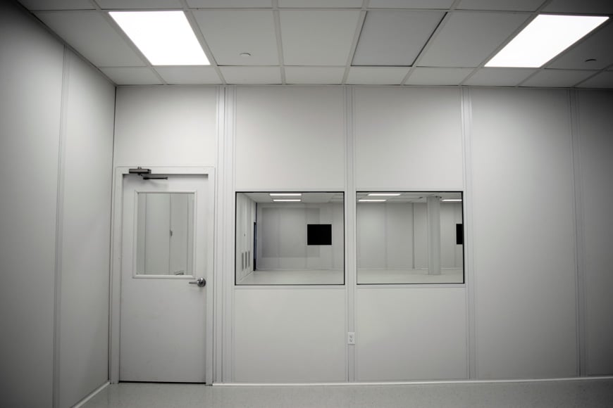
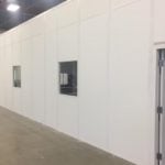
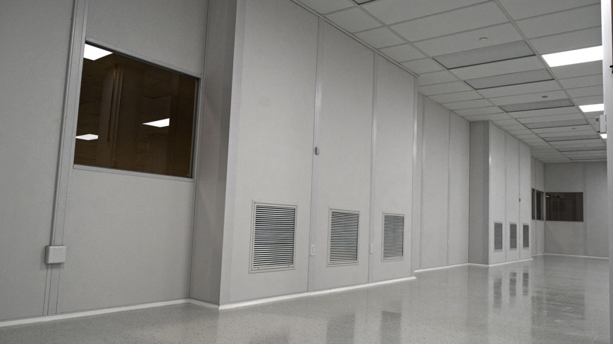
Virtually all medical device cleanrooms have a positive pressure design which operates 24/7. Inside the cleanroom, the increased pressure is not overtly noticeable beyond the entry and exit. Optimized delivery and well-placed air returns ensure that air flow unidirectionally from the introduction point to the exit point.
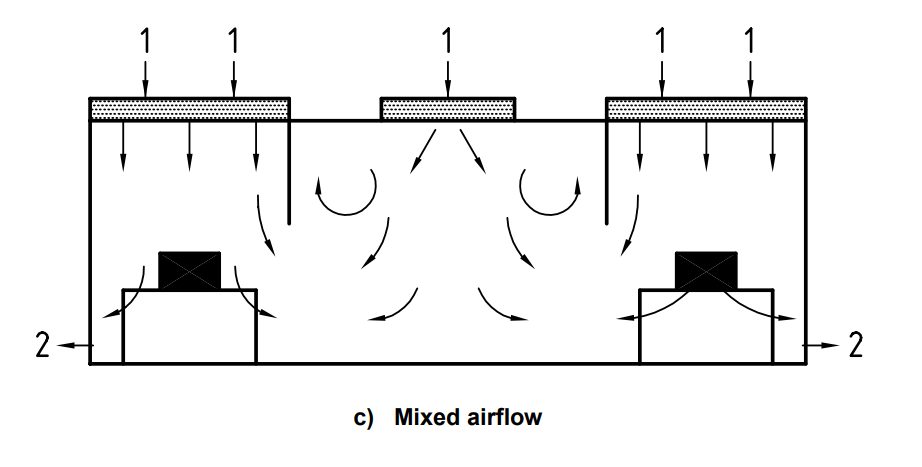
The airflow in an ISO 7 / ISO 8 cleanroom is generally defined as “non-unidirectional” or “mixed airflow”. Mixed airflow patterns demonstrate both laminar flow (unidirectional) and non-unidirectional airflow where the air mixes during induction.
Cleanroom HVAC Efficiency and Behavioral Metrics
During cleanroom calibration and HVAC balancing, we’ll inspect, measure, and adjust each system to what will eventually become its most efficient operating state:
- Air supply and return system
- Functional intake and exhaust systems
- Air changes per hour
- Room pressure
- Balance of airflow
Characterizing Problematic Air Behaviors
Consider other air principles that influence HVAC performance: Cleanroom air quality variables include:
- Air temperature
- Air movement (direction, velocity)
- Mixing potential
- Supply and return flow conditions, to include pressure differences between surrounding areas
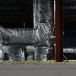
- Sources of tempered and untempered make-up air
- Influence of existing HVAC systems
- Effects of weather and season
Troubleshooting Fan Filter Operation
Adequate Power Supply
It’s important that each fan filter receives enough power to attain equilibrium in its power curve. In this case, the 115V motors required ~35% minimum fan speed for enough power to drive the impeller.
The cleanroom cannot be balanced until all of the fan filter units are placed and tested for sufficient airflow. Each fan filter is tested individually before the water column or air change calibration. In this case, PAC specialists specified each of the FFU’s at an airflow rate of ~350 CFM.
If a fan filter is not achieving proper airflow, it could be because:
- It’s defective
- Improperly installed
- Damaged before installation
- Not turned on
- Not receiving power
- Not receiving enough power
- Not wired properly
- Not wired at all
- Not configured properly or not on the right setting
- Not receiving adequate air supply or room is overpressurized
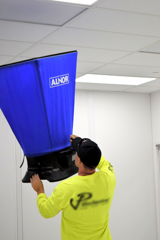
Airflow Testing Equipment – Airflow Hoods
An airflow capture hood provides fast response and repeatable results in high flow scenarios. The hood below is a 2 x 2 footprint which takes the CFM, air speed, and velocity. The direct readout and long reach is a welcomed solution for high ceilings and avoids the need for a ladder. The sensors provide back pressure compensation at high flow rates and automatically sense supply or return air. The geometric fit to the 2 x 4 fan filter units ensure consistent placement and accurate readings. The large surface area renders results faster, as the measurements do not require multiple sampling points or surface area calculation.
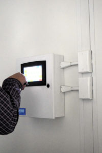
Diagnosing Fan Filter Control and Communication Issues
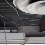
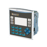
Each fan filter is wired to an Ethernet signal via a chained by CAT5 cables running to control boxes on the fan filter units. A central controller and display screen outside the cleanroom provides micro and macro control for 16 – 400 FFUs and a configuration of 8 – 25 different rooms or groups of fan filters.
Troubleshooting Fan Filter Communication and Error Logs
In this case, two fan filter units were not properly wired to the main controller causing errors in roughly half of the room’s fan filters. The units were receiving power but not communicating with the control system because of the wiring issue. The system allowed us to review the status and error codes of each filter, jump-start them, observe the start sequence, and find the exact filter for investigation. Without a smart system in place, identifying the source of the problem might take an entire day just to check each filter link one by one. Here, we were able to identify and make a fix within a few minutes.
An integrated fan filter controller makes everyone’s job easier and gets you operational faster.
Central control and remote capabilities reduce variables and identify problems faster. On/off, fan speed, status, alarms, fan RPM, and error logs are available directly from the console or PC browser. Most problems are diagnosed by a quick scan of the error codes.
Balancing with Remote Cleanroom Fan Filter Controllers
The central controller integrates the data from both the thermostats, fan filter processors, and room-side environmental sensors. Fan filter speed is then adjusted by each group to achieve the specified room pressure while also meeting the ideal temperature and humidity. Each group of fan filters is then adjusted in unison to maintain a balanced and uniform movement of air throughout the cleanroom.
A differential pressure relay within the cleanrooms plenum measures the pressure differences of shared walls to the central controller. Adjusting the airflow of each room independently through the central controller allows calibration and monitoring in real-time.
Each space of the cleanroom is adjusted independently to achieve balance and proper pressure differential between each cascading room.
Get as Close to Final Operating State as Possible
There are some components of the cleanroom that might be awaiting installation such as the door trim and passthrough boxes. Cover any low gaps for a temporary air barrier. At this point were not looking at the air cleanliness, directional flow, or air velocity on a granular level. These will all be measured and validated during the ISO validation by a third party.

Consider external factors such as parallel air systems, the cleanliness of surrounding spaces, and ambient temperature outside the cleanroom. Get these factors as close to expected real time operations for repeatable results during final testing.
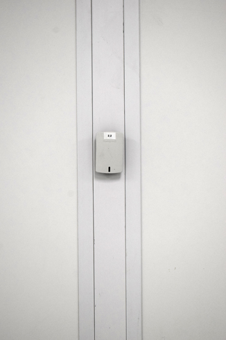
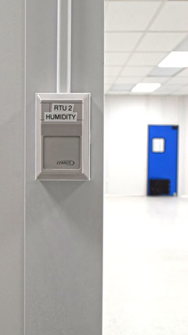
Cleanroom Air Temperature and Humidity Management
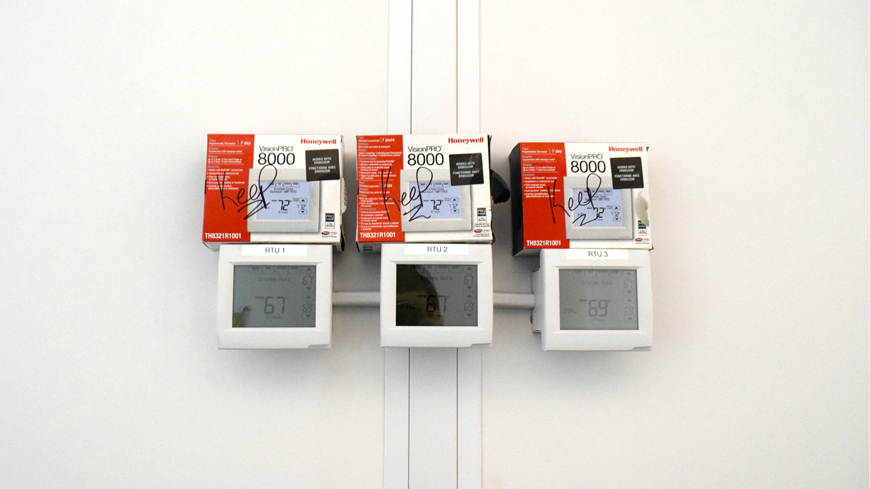
Air temperature and humidity control in cleanrooms require special measures for zone-to-zone control. Here, each zone requires multiple independent sensors and readouts for temperature, humidity, and water column (wc).
Overcoming Thermal Pitfalls with Computational Algorithms
Here’s some manufacturer-direct info from Honeywell on the advanced features of the thermostat controls specified for this project.
A conventional mechanical or electronic thermostat does not control temperature precisely at setpoint. Typically there is an offset (drop) in the control point as the system load changes. This is a phenomenon that most people in the industry know and accept.
Many factors contribute to offset including switch differential, thermal lag, overshoot, cycle rates, and system load. The thermostat microprocessor simultaneously gathers, compares and computes data. Using this data, it controls a wide variety of functions. The algorithm (program) in the thermostat eliminates the factors causing offset. This makes temperature control more accurate than conventional mechanical or electronic thermostats.
The temperature control algorithm is called proportional plus integral (P+I) control. The thermostat sensor, located on the thermostat or remote, senses the current space temperature. The proportional error is calculated by comparing the sensed temperature to the programmed setpoint. The deviation from the setpoint is the proportional error. The thermostat also determines the integral error, which is a deviation based on the length of error time. The sum of the two errors is the (P+I) error. The cycle rate used to reach and maintain the setpoint temperature is computed using the P+I. The addition of the integral error is what differentiates the thermostat from many other electronic and mechanical thermostats.
Honeywell
This system performed almost exactly to its specified requirements with a few customizations for the desired pressure balance. As the filter load increases and production begins, the control unit allows incremental correction of environmental factors, changing production needs, or ambient conditions.
The contents herein are considered educational and do not represent nor suggest a recommendation for your facility. Precise cleanroom airflow management is complicated and hands-on. There’a lot of preliminary engineering required before any room-specific mechanical drawing.
The exact calibration process is something that’s unique to each operation, the equipment at hand, and the system in place. If you have questions, please give us a call or send us an email.
Cleanroom construction balances interworking of 5 – 6 different teams on tight schedules. Most of these teams provide expertise only to their unique trade and have little on-site interaction throughout the project unless otherwise specified.
Final Considerations
- What type of cleanroom system best fits your needs
- Obvious construction barriers such as requirements for elevators, fire safety, and electrical capacity
- Equipment size and integration with regard to mechanical, electrical, and plumbing requirements
- Ergonomic workflow and process workflow based on the application
- Look, aesthetics, and preference
- Project management capacity and identifying internal project leads
- Accommodations of the end-user
Don’t forget about the most essential aspect of cleanroom production: the people and equipment required for end-use. Forecasting the end-user experience must factor light levels, noise, temperature, workflow, heat load, and cleanroom outfitting choices.
How Can We Help?
The advantage of a PAC cleanroom is that it’s built from the ground up based on your needs. While some might suspect “custom-built” means “custom expensive” — that’s not the case. Custom-built plainly means you get what you need — let’s skip everything you don’t. That’s the advantage of a modular cleanroom.
Because we specify and source the entire build, we’re intimately familiar with every detail. That’s the only way we can guarantee that it meets the final ISO validation as specified in the original design.
We coordinate installation services and engineering internally which reduces the complexity of localized installation. We’re able to schedule and work out most issues directly with the manufacturers, vendors, and onsite plumbing, mechanical, and electrical. As an added value, PAC’s full-circle medical device supply equipment and consumables provide both expertise and a single-invoice supply channel that gets you up and operational faster.